Welcome to Sino Bearings web
24x7 HOTLINE:+86-28-81454188
 PRODUCTS
 CAR BEARINGS
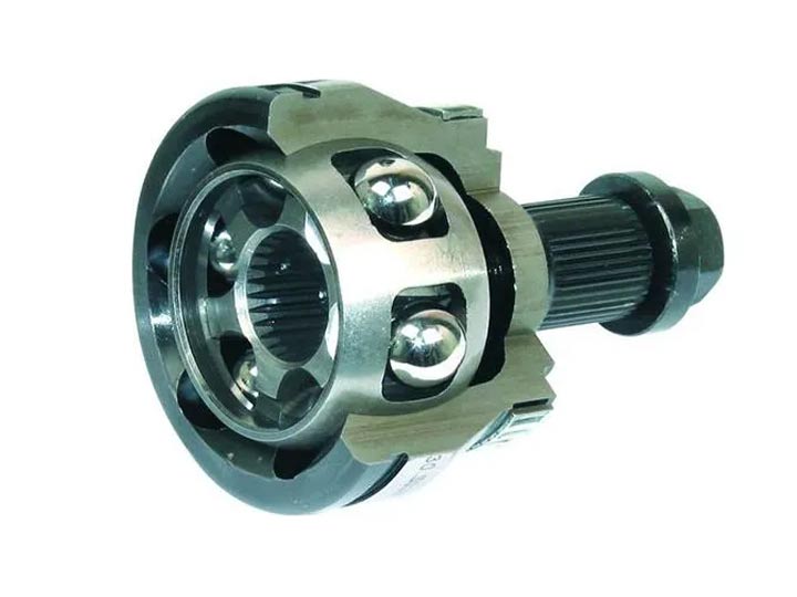
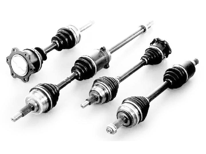
Constant-velocity joints (also known as homokinetic or CV joints) allow a drive shaft to transmit power through a variable angle, at constant rotational speed, without an appreciable increase in friction or play. They are mainly used in front wheel drive vehicles. Modern rear wheel drive cars with independent rear suspension typically use CV joints at the ends of the rear axle halfshafts and increasingly use them on the drive shaft.
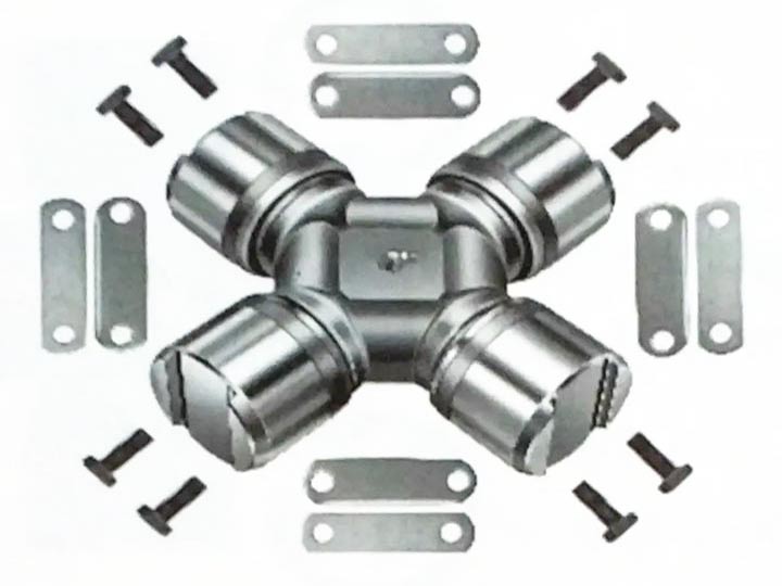
The universal joint, one of the earliest means of transmitting power between two angled shafts, was invented by Gerolamo Cardano in the 16th century. The fact that it failed to maintain constant velocity during rotation was recognized by Robert Hooke in the 17th century, who proposed the first constant velocity joint, consisting of two Cardan joints offset by 90 degrees, so as to cancel out the velocity variations. This is the "double Cardan". Many different types of constant-velocity joints have been invented since then.
Early front wheel drive systems such as those used on the 1930s Citroën Traction Avant and the front axles of Land Rover and similar four wheel drive vehicles used universal joints, where a cross-shaped metal pivot sits between two forked carriers. These are not CV joints as, except for specific configurations, they result in a variation of the angular velocity. They are simple to make and can be tremendously strong and are still used to provide a flexible coupling in some propshafts, where there is not very much movement. However, they become "notchy" and difficult to turn when operated at extreme angles.
As front-wheel drive systems became more popular, with cars such as the BMC Mini using compact transverse engine layouts, the shortcomings of universal joints in front axles became more and more apparent. Based on a design by Alfred H. Rzeppa which was filed for a patent in 1927[1] (a CV joint, the Tracta joint, designed by Pierre Fenaille at Jean-Albert Grégoire's Tracta company was filed for patent in 1926[2]), constant velocity joints solved many of these problems. They allowed a smooth transfer of power despite the wide range of angles through which they were bent.
The Tracta joint works on the principle of the double tongue and groove joint. It comprises only four individual parts: the two forks (a.k.a. yokes, one driving and one driven) and the two semi-spherical sliding pieces (one called male or spigot swivel and another called female or slotted swivel) which interlock in a floating (movable) connection. Each yoke jaw engages a circular groove formed on the intermediate members. Both intermediate members are coupled together in turn by a swivel tongue and grooved joint. When the input and output shafts are inclined at some working angle to each other, the driving intermediate member accelerates and decelerates during each revolution. Since the central tongue and groove joint are a quarter of a revolution out of phase with the yoke jaws, the corresponding speed fluctuation of the driven intermediate and output jaw members exactly counteracts and neutralizes the speed variation of the input half member. Thus the output speed change is identical to that of the input drive, providing constant velocity rotation.[3][4][5]
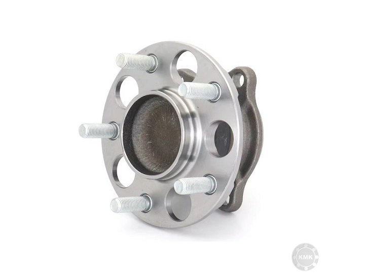
A Rzeppa joint (invented by Alfred H. Rzeppa in 1926) consists of a spherical inner shell with 6 grooves in it and a similar enveloping outer shell. Each groove guides one ball. The input shaft fits in the centre of a large, steel, star-shaped "gear" that nests inside a circular cage. The cage is spherical but with ends open, and it typically has six openings around the perimeter. This cage and gear fit into a grooved cup that has a splined and threaded shaft attached to it. Six large steel balls sit inside the cup grooves and fit into the cage openings, nestled in the grooves of the star gear. The output shaft on the cup then runs through the wheel bearing and is secured by the axle nut. This joint can accommodate the large changes of angle when the front wheels are turned by the steering system; typical Rzeppa joints allow 45°–48° of articulation, while some can give 54°.[6] At the "outboard" end of the driveshaft a slightly different unit is used. The end of the driveshaft is splined and fits into the outer "joint". It is typically held in place by a circlip.


The Birfield joint is a type of constant-velocity joint based on the Rzeppa joint, but with the six balls confined using elliptical tracks rather than a cage. They have improved efficiency and are widely used in modern cars for the outboard driveshaft joints.[7] The Birfield joint was developed by Birfield Industries and came into widespread use with the development of front-wheel drive cars such as the Mini.[8]
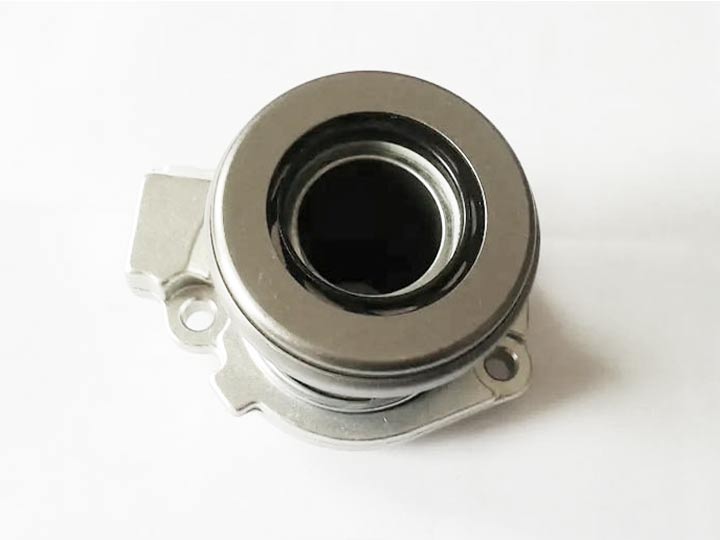
A Weiss joint consists of two identical ball yokes which are positively located (usually) by four balls. The two joints are centered by means of a ball with a hole in the middle. Two balls in circular tracks transmit the torque while the other two preload the joint and ensure there is no backlash when the direction of loading changes.
Its construction differs from that of the Rzeppa in that the balls are a tight fit between two halves of the coupling and that no cage is used. The center ball rotates on a pin inserted in the outer race and serves as a locking medium for the four other balls. When both shafts are in line, that is, at an angle of 180 degrees, the balls lie in a plane that is 90 degrees to the shafts. If the driving shaft remains in the original position, any movement of the driven shaft will cause the balls to move one half of the angular distance. For example, when the driven shaft moves through an angle of 20 degrees, the angle between the two shafts is reduced to 160 degrees. The balls will move 10 degrees in the same direction, and the angle between the driving shaft and the plane in which the balls lie will be reduced to 80 degrees. This action fulfills the requirement that the balls lie in the plane that bisects the angle of drive. This type of Weiss joint is known as the Bendix-Weiss joint.
The most advanced plunging joint which works on the Weiss principle is the six-ball star joint of Kurt Enke. This type uses only three balls to transmit the torque, while the remaining three center and hold it together. The balls are preloaded and the joint is completely encapsulated.[9][10]
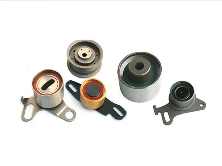
Tripod joints are used at the inboard end of car driveshafts. The joints were developed by Michel Orain, of Glaenzer Spicer of Poissy, France. This joint has a three-pointed yoke attached to the shaft, which has barrel-shaped roller bearings on the ends. These fit into a cup with three matching grooves, attached to the differential. Since there is only significant movement in one axis, this simple arrangement works well. These also allow an axial 'plunge' movement of the shaft, so that engine rocking and other effects do not preload the bearings. A typical Tripod joint has up to 50 mm of plunge travel, and 26 degrees of angular articulation.[11] The tripod joint does not have as much angular range as many of the other joint types, but tends to be lower in cost and more efficient. Due to this it is typically used in rear wheel drive vehicle configurations or on the inboard side of front wheel drive vehicles where the required range of motion is lower.
Double Cardan joints are similar to double Cardan shafts, except that the length of the intermediate shaft is shortened leaving only the yokes; this effectively allows the two Hooke's joints to be mounted back to back. DCJs are typically used in steering columns, as they eliminate the need to correctly phase the universal joints at the ends of the intermediate shaft (IS), which eases packaging of the IS around the other components in the engine bay of the car. They are also used to replace Rzeppa style constant-velocity joints in applications where high articulation angles, or impulsive torque loads are common, such as the driveshafts and halfshafts of rugged four wheel drive vehicles. Double Cardan joints require a centring element that will maintain equal angles between the driven and driving shafts for true constant velocity rotation.[12][13] This centering device requires additional torque to accelerate the internals of the joint and does generate some additional vibration at higher speeds.[14]
The Thompson constant velocity joint [15] (TCVJ), also known as a Thompson coupling, assembles two cardan joints within each other to eliminate the intermediate shaft. A control yoke is added to keep the input and output shafts aligned. The control yoke uses a spherical pantograph scissor mechanism to bisect the angle between the input and output shafts and to maintain the joints at a relative phase angle of zero. The alignment ensures constant angular velocity at all joint angles. Eliminating the intermediate shaft and keeping the input shafts aligned in the homokinetic plane greatly reduces the induced shear stresses and vibration inherent in double cardan shafts.[16][17][18] While the geometric configuration does not maintain constant velocity for the control yoke that aligns the cardan joints, the control yoke has minimal inertia and generates little vibration. Continuous use of a standard Thompson coupling at a straight-through, zero-degree angle will cause excessive wear and damage to the joint; a minimum offset of 2 degrees between the input and output shafts is needed to reduce control yoke wear.[19] Modifying the input and output yokes so that they are not precisely normal to their respective shafts can alter or eliminate the "disallowed" angles.[20]
The novel feature of the coupling is the method for geometrically constraining the pair of cardan joints within the assembly by using, for example, a spherical four bar scissors linkage (spherical pantograph) and it is the first coupling to have this combination of properties.[21]
The coupling earned its inventor, Glenn Thompson, the Australian Society for Engineering in Agriculture Engineering Award.[22]
|
|
Designed and patented by Antonio Malpezzi[citation needed] (at the time owner of a CV remanufacturing company in Italy) in 1976, this joint consists of a cage with a spherical inner with a shaped mouth. The input shaft fits on the centre of a sphere with two rectangular grooves. To assemble it, the spherical driving ball is inserted in the cage by matching the two grooves with the narrowest part of the cage's mouth, rotated 90°. Then two steel blocks are inserted in the grooves and locked in place with a bolt running through the cage's side.
This joint was extensively tested for possible automotive application but proved to be unable to cope with the articulation needed for such a use. It was widely used in Italy in agriculture[citation needed], as it was better suited than a Cardan joint to rotate at high speed and cheaper than a Rzeppa joint. By the early '90s, with the appearance on the market of Rzeppa joints produced in Asia, its production became uneconomic and it was discontinued.
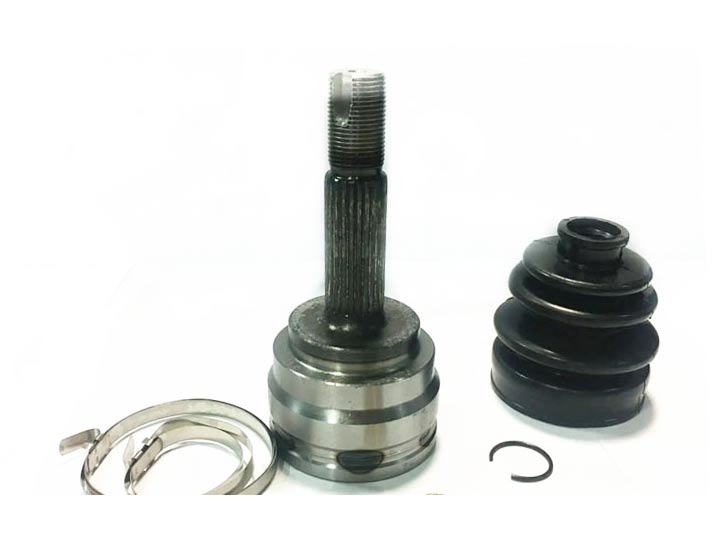
Constant-velocity joints are protected by a rubber boot, a "CV gaiter", usually filled with molybdenum disulfide grease. The six spheres are bounded by an anti-fall gate that prevents the spheres from falling when the shaftings are perfectly aligned. Cracks and splits in the boot will allow contaminants in, which would cause the joint to wear quickly as grease leaks out. (Parts in contact would not get proper lubrication, small particulates would cause damage and scratching, while water ingress causes metal components to rust and corrode.) Wear of the boot often takes the form of small cracks, which appear closer to the wheel,[citation needed] because the wheel produces most of the vibration and up and down motions. Cracks and tears in the areas closer to the axle are usually caused by external factors, such as packed snow, stones or uneven rocky off-road paths. Aging and chemical damage can also cause boot failure.
We supply high quality KMK brand bearings, chains, belts, oil seals, snap rings.... We can also do OEM for your own brand. Contact our sales team sales@sinobearings.com for quick response.
 INQUIRY
 +86-28-81454188


.gif)