Welcome to Sino Bearings web
24x7 HOTLINE:+86-28-81454188

 TECHNOLOGY
by Harvey Nixon, Thomas Springer, Michael Hoeprich, Douglas Clouse, The TIMKEN COMPANY
Debris particle contamination in lubricants has been identi?ed as a major cause of premature bearing and gear failure, with accompanying costs in equipment downtime, warranty, and lost productivity. Various experimental and predictive methods have been developed to assist the design engineer in analysis and development of equipment that is less sensitive to such contamination. This paper provides an overview and new data comparing bearing life test results and predictive analysis methods for various tapered roller bearings operating under debris-contaminated conditions. Recent work has re?ned one analytical method (using a surface characterization technique), correlated this method with bearing test lives in debris conditions, and pointed to design and manufacturing modi?cations in the bearings themselves, making the bearings live longer in debris-contaminated environments.
Contamination Characterization
Equipment design engineers have many contaminated lubricant analysis tools to help them assess the detrimental effects of debris particles on machinery wear and by their use can monitor the resulting loss in performance [1, 2, 3, 4]. Others are aimed at understanding the material make-up and characteristics of the lubricant contamination [5]. Most of the analysis tools just mentioned are used in monitoring and understanding the evolution of equipment failure, as well as the level of lubricant contamination for predicative and preventative maintenance. But they do little in helping to evaluate the impact debris damage has on ?nished gear and bearing surfaces as it relates to fatigue life of their materials.
Surface Characterization Method
Nixon and Cogdell developed a method for assessing the detrimental effect of debris contaminated lubrication environments [6] which is appropriately labeled Debris Signature AnalysisSM. The following ?eld study, conducted in cooperation with an equipment manufacturer, is an example of the advantage that such a surface characterization method might provide in evaluating equipment systems. The standard method for determining particle size distributions and concentration levels was used to monitor contamination levels in an actual customer ?eld application. Bearings from these ?eld units were then removed from service after an extended period of time and examined for debris damage both visually and by the surface characterization method in order to quantify the damage levels. Table 1 shows a few typical particle size distributions and concentrations observed through the period of service by the equipment. Figure 1 shows a typical visual appearance of some of the bearing load carrying surface after the same period of service.


FIGURE 1 – Micrograph of typical bearing load carrying surface with extremely large dent
It was quite evident in just these visual comparisons alone that the lubricant analysis did not illustrate the level of surface damage that might be expected. By a comparison of the data in Table 1 to the damage evident by the visual appearance, it is certain that the lubricant sampling did not predict any particles much greater than 300 um in size. However, the visual comparison of dents, some on the order of 6 mm in diameter, indicates the presence of huge particles on the order of 100 times larger than the 300 um size particle from the lubricant sample. The Debris Signature AnalysisSM method was used to more accurately characterize the surface damage and indicated a 42% life reduction would be predicted. This example serves to illustrate the need for surface characterization in linking performance to contamination damage.
Product Performance Comparisons
As part of the evaluation process for assessing and predicting bearing performance under conditions of debris contamination, numerous bearing life tests have been run and a standardized method to apply debris damage was used [7]. Tested bearings were pre-dented and no additional debris was added during these tests.
In Figure 2, the performance comparison for ?ve major tapered roller bearing manufacturers is shown. This testing was previously reported [8] and was performed on what is considered to be standard product, manufactured with the conventional process common to each given manufacturer. The results within this group varied by a factor of about three with Brg A having the highest relative performance. Brg B and Brg E used through hardened material and processing, the other bearings C & D were manufactured in part or completely of case carburized components.

FIGURE 2 – Life test comparison, bearing outer diameter 73 mm
For statistical comparison purposes, the life test results are shown bracketed with 65% con?dence bands. The width of these bands is calculated based on the sample size and scatter of testing failures and is a function of the Weibull slope. When such bands overlap between test groups, no statistically signi?cant difference in performance can be claimed at the 90% con?dence level.
Testing Of Conventional Versus Special Debris Resistant Bearings
Testing has also been performed with a conventional product from one manufacturer (Brg A) and special “debris resistant” products from two other manufacturers. Here the special debris resistant products were claiming up to ten times life improvement over conventional processes.
Figure 3 shows the normalized results for debris damage testing with conditions identical to Figure 2. In this Brg A had life test results that slightly exceeded the results of the special bearing.

FIGURE 3 – Life test comparison of conventional versus special “debris resistant” bearing (outer diameter 83 mm)
Figure 4 shows the normalized life test results with conditions similar to that of Figure 2, except the debris media was changed. This resulted in only light debris damage being incurred. Here Debris Signature Analysis was applied to conventional Brg A, and predicted only threshold life reduction due to debris. Under these conditions, Brg A had performance results that were equal to the results of the special bearing.
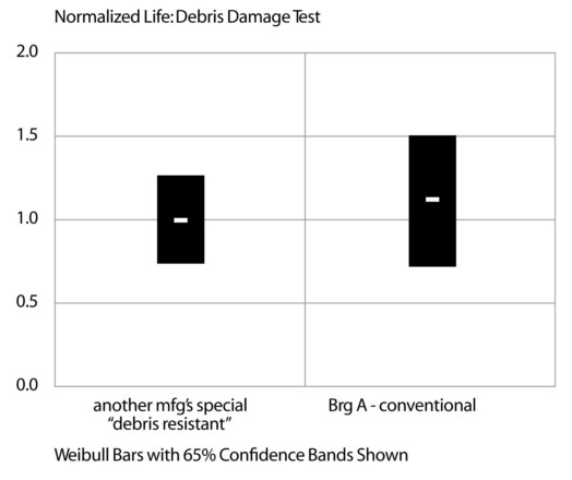
FIGURE 4 – Life test comparison of conventional versus special “debris resistant” bearing (outer diameter 68 mm)
Figure 5 shows the normalized results with a large, 318 mm outer diameter bearing. A different set of life testing conditions was applied (caused in part by the use of the larger test bearing) as well as new debris media and new method to apply the debris media. This resulted in moderate-to-severe debris damage. Debris Signature Analysis was applied to conventional Brg A and predicted up to a 3 times life reduction. Under these conditions, Brg A had life test results that signi?cantly exceeded the results of the special bearings.
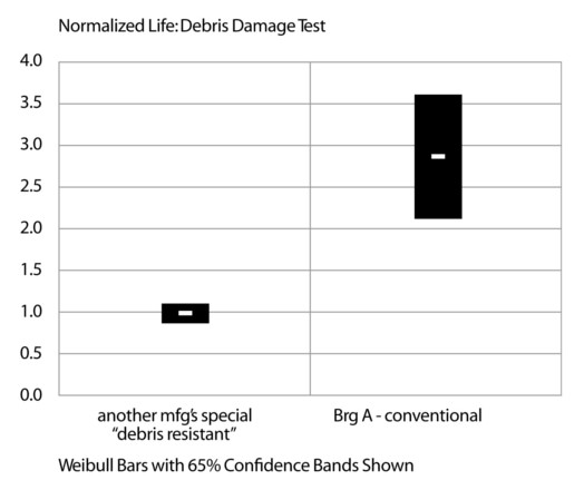
FIGURE 5 – Life test comparison of conventional versus special “debris resistant” bearing (outer diameter 318 mm)
One conclusion from this testing is that differences in the manufacturing process, materials and metallurgical practices used in bearings produced by different manufacturers impacts fatigue life of bearings operating in high debris environments.
Raising The Performance Level
By studying the unique metallurgical design and processing parameters used to produce Brg A, an improved debris resistant approach was developed. The goal was to enhance the bearing mechanical properties of strength, ductility and toughness, particularly at the functional contact (raceway) surfaces. The approach included change to key design speci?cations and the tightening of process control limits for select parameters particularly during heat treat. The proprietary speci?cation involves select parameters including material chemistry, retained austenite, microstructure, and post heat treat control of near surface properties.
The performance results of this new debris resistant design and processing approach are shown in Figure 6. In this particular testing scheme the lives of two debris dented conventional baseline groups were approximately 2 to 3 times less than the predicted life with no denting. Debris Signature Analysis was applied and predicted a debris life reduction factor between 0.4 to 0.5. for these baseline bearings.
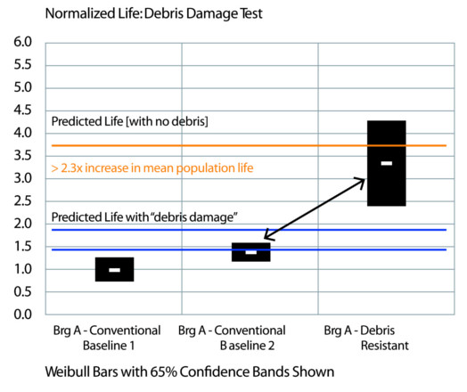
FIGURE 6 – Life test comparison of special “debris resistant” versus conventional bearing (outer diameter 248 mm)
The debris resistant bearing performance was shown to be much higher than the baseline groups with its upper 65% con?dence band crossing the line for predicted life with no debris damage. Thus the new debris resistant bearing negated the effects of the given debris damage and increased mean population bearing life by up to 2.3 times over the two baseline bearing groups made with conventional processing. This debris resistant bearing is currently being offered as providing up to 2 times life improvement in debris environments.
Life Prediction Model
The theoretical basis for the debris life prediction tool was presented by Ai [12] wherein the effects of debris dents on raceway contact stresses and fatigue life are determined. The model was veri?ed with controlled debris dent bearing tests using bearings with the performance characteristics represented by Brg A.
Since debris in applications covers a large range of particle sizes, a program was put together to determine the effect of lubricant contamination composed of realistic particle size distributions. Two approaches were used. The ?rst approach simulated debris particle size distributions that correlate to ISO 4406 code distributions. 52100 steel debris particle distributions for ISO 13/10, 15/12, 17/14, 18/16, and 21/18 were mixed with lubricant and used to dent bearings as explained by Nixon [7]. As an example, Figure 7 shows the particle distributions used for the ISO 4406 21/18 and 15/12 cleanness levels. These distributions were developed from the analyses and ISO 4406 characterization of debris contaminated used oil. The dented bearing surfaces were then optically mapped to obtain dent size and surface density distributions. Thus obtaining a Debris Signature AnalysisSM pro?le for each of these debris conditions. Data ?les containing dent sizes and surface densities were stored for use by application engineers in analyzing the life of bearings which might be operating in these environments.

FIGURE 7 – Particle size distributions for two specific ISO codes
The second approach was to obtain bearings from actual applications in the ?eld and optically characterize the sizes and surface density of dents on these bearings for future life analyses. These were larger bearings that generally operate in more heavily contaminated conditions and cannot be adequately described by ISO 4406. Photographs of these dented surfaces can then be used by engineers to select a level of raceway surface damage typically seen in their applications.
The analysis of typical life test lubricant taken from standard life test machines have shown that the base cleanness level is ISO 15/12. The debris life factor has a value of 1.0 at this cleanness level. Cleaner lubricant would provide enhanced life and lubricant with more debris would give a reduced life.
To determine a life reduction factor, the dent Debris Signature AnalysisSM data ?les are then used in the following manner. The rolling element contact loads are determined for application conditions so as to determine contact stresses and contact area. The effect of the size and number of dents on the life of the bearing in this environment can then be determined. Figure 8 shows a plot of debris life factors (a3D) for a 33 mm bore tapered roller bearing for different lubricant cleanness levels and radial loads in terms of percent C(90) rating. It can be seen that at heavy loads the effect of varying debris levels is reduced because the net effect on the general stress level is reduced as opposed to the greater effect on modifying the general stress level at light loads.
In Figure 2, it is shown that bearings made of through hardened steel can be more sensitive to debris dents than bearings made of case carburized steel. Figure 6 shows that case carburized bearings can be made even more debris resistant. Figure 9 shows the difference in model debris life factors for bearings made of these materials relative to case carburized bearings for a moderately contaminated environment. Bearings made of through hardened steel will have a somewhat lower life than case carburized bearings. As might be expected, the debris resistant bearing microstructure is seen to be more effective in improving bearing life in the more contaminated environments.
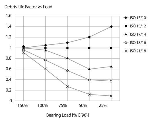
FIGURE 8 – Debris life adjustment as a function of load and various ISO codes
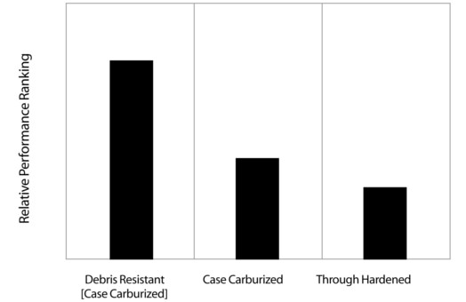
FIGURE 9 – Relative debris life factor for bearing materials
A signi?cant number of debris dented bearings have been life tested in the authors’ life test machines. The correlation between the experimentally determined reduction in life due to debris dents and the life reduction predicted by this approach is shown in Figure 10. [15] For the authors’ bearing product, this model has been shown to provide a practical connection between actual debris dents and subsequent fatigue damage.

FIGURE 10 – Comparison of experimental results with model predictions
Conclusions
The following conclusions and observations are provided as a result of the analysis experience and experimental test results.
1) For heavily contaminated systems, lubricant analysis methods alone might not be a reliable method for linking bearing damage and the resulting ?eld service.
2) Fatigue life testing of bearings to evaluate debris damage sensitivity, can be a useful tool to differentiate performance of products.
3) Standardized life testing with debris showed that conventional and debris resistant bearings from various manufacturers perform at signi?cantly different levels. These differences should be considered when making comparisons concerning the relative hierarchy of product debris resistance and when applying performance prediction tools.
4) The direct measurement of damage method encompassed by Debris Signature AnalysisSM is expected to provide more precision over other approaches involving lubricant contamination analysis in quantifying damage differences.
5) Debris Signature AnalysisSM should provide a tool for comparing, in a quanti?able way, the contamination environments of successful equipment performance to those that are not successful.
6) The new life prediction model provides a practical connection between actual debris dents and subsequent fatigue damage.
References
1 Anderson, D. P., “Wear Particle Atlas (Revised),” Predict/DLI, Cleveland, OH, 1995.
2 Anonymous, “Standard Test Method for Insoluble Contamination of Hydraulic Fluids by Gravimetric Analysis,” ASTM D4898-90, ASTM, W. Conshohocken, PA, 1996
3 Glaeser, W. A., “Use of Surface Analysis Techniques in the Study of Wear,” Wear, Vol. 100, No. 1-3, pp. 477-487, December 1984
4 Ives, L. K., “Electron Microscopy,” ASM Handbook, Vol. 18, Friction, Lubrication and Wear Technology, ASM International, 1995
5 Poley, J., “Oil Analysis for Monitoring Hydraulic Oil Systems, A Step-Stage Approach,” Lubrication Engineering, Vol. 46, No. 1, 1990 pp 41-47
6 Nixon, H.P., Cogdell, J. D., “Debris Signature AnalysisSM: A Method for Assessing the Detrimental Effect of Speci?c Debris Contaminated Lubrication Environments”, SAE Paper 9814781998
7 Nixon, H.P., Zantopulos, H., Cogdell,J.D.,“A Standardized Method for Evaluating Debris Resistance of Rolling Element Bearings,” SAE Tech. Paper Series 940728, (1994)
8 Nixon, H.P., Ai, Xiaolan, Cogdell, J.D., Fox, G.P., “Assessing and Predicting the Performance of Bearings in Debris Contaminated Lubrication Environment”, SAE Paper 1999-01-2791
9 Ai, Xiaolan and Nixon, Harvey P., “Fatigue Life Reduction of Roller Bearings Due to Debris Denting: Part I – Theoretical Modeling,” Tribology Transactions, Vol. 43 (2000),2, pp. 197-204
10 Ai, X., “Effects of Debris Contamination on the Fatigue Life of Roller Bearings”, 2001
All images: The Timken Company
KMK BEARINGS