Welcome to Sino Bearings web
24x7 HOTLINE:+86-28-81454188

 NEWS
NEWS
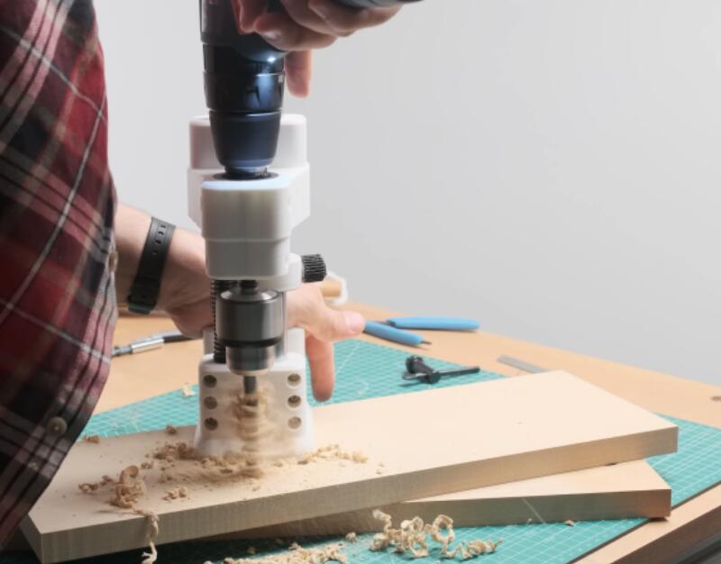
Typically we often don’t cover paid products here on Hackaday, but we couldn’t help but be impressed with this 3D printed drill guide from [USSA]. While you’ll need to pay the toll to access the STL files and plans, there’s an excellent video showing a bit of magic behind the curtain that you can check out free of charge. There are several interesting insights and some great techniques put into this design that anyone could take and apply to their own project.
First, what is a drill guide? Many of us don’t have the luxury of a full-sized drill press, so we have to make do with a hand drill. There are various jigs and tricks to get straighter holes, but it can be frustrating to mark out threaded screw inserts with great precision only to discover all the inserts are at an angle and the circuit board won’t fit. A drill guide ensures holes are plunged straight up and down and at a reliable depth.
[USSA] starts by showing the node-based CAD that makes up the design (a program called Grasshopper). As he assembled it, simple nuts and screws held it together. But rather than clamp two separate pieces together, the screws compress the single plastic with a clever slot in the side to allow the plastic to flex. Several 3D printed jigs were used for assembling the bearing shaft. Ultimately the results look quite impressive, and it’s an inspiration for our own printed projects.